Global
  English
 中文简体
中文简体 русский
 Español
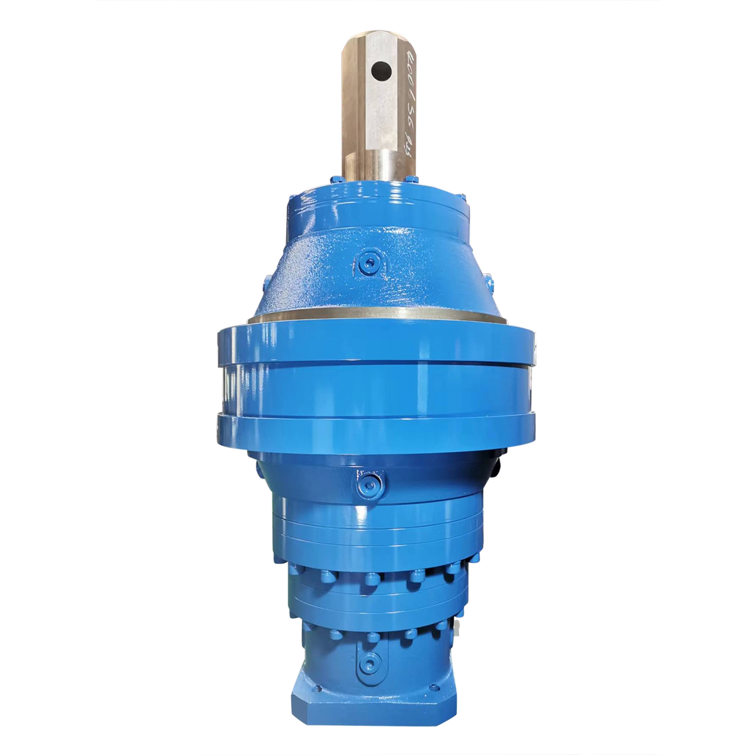
Key feature:Planetary gearbox is produced by modular design, and can be combined according to client...
See Details
News Directory
An industrial planetary gearbox operates by sharing torque across multiple external spur gears rotating around a centralized drive axis, offering exceptional torque density and coaxial structural alignment. To understand how does planetary gear work, the mechanical assembly distributes input rotation from a central sun gear to surrounding planet gears that mesh within a stationary outer ring gear, splitting the mechanical load evenly across multiple gear contact points. This epicyclic arrangement provides high torsional stiffness and allows for large speed reductions in a compact space, making it a standard choice for high-precision servo applications, heavy industrial automation, and automotive powertrains where efficiency metrics must exceed ninety-seven percent per stage.
Examining how planetary gearbox works requires identifying the three primary components of the epicyclic train: the central sun gear, the planet gears mounted on a rotating carrier frame, and the outer ring gear housing. Input rotational energy from an electric motor typically drives the central sun gear directly. As the sun gear rotates, its teeth mesh with the surrounding planet gears, forcing them to rotate on their own shafts.
Because the outer ring gear is held fixed within the gearbox chassis, the spinning planet gears are forced to walk along the internal circumference of the ring. This collective movement rotates the planet carrier assembly. The output shaft is keyed directly to this carrier, converting the high-speed, low-torque input into a low-speed, high-torque output with zero axial offset. Sharing the torque load among three or four planet gears cuts individual tooth stress significantly, reducing wear compared to traditional inline gear sets.
Engineers designing mechanical drive systems must know exactly how to find gear ratio of planetary gearbox assemblies to ensure output speeds match design requirements. The overall reduction ratio depends entirely on the number of teeth on the sun gear and the outer ring gear, while the tooth count of the individual planet gears does not affect the final ratio.
When the outer ring gear is held stationary and the sun gear acts as the input while the planet carrier provides the output, the exact mechanical advantage is calculated using a standard formula: the ratio equals one plus the total number of ring gear teeth divided by the number of sun gear teeth. The analytical matrix below details common tooth configurations and their resulting performance metrics.
| Sun Gear Teeth (Ns) | Ring Gear Teeth (Nr) | Planet Teeth (Np) | Exact Mechanical Formula | Final Reduction Ratio |
| 12 Teeth | 60 Teeth | 24 Teeth | 1 + (60 / 12) | 6.00:1 Reduction |
| 18 Teeth | 72 Teeth | 27 Teeth | 1 + (72 / 18) | 5.00:1 Reduction |
| 24 Teeth | 96 Teeth | 36 Teeth | 1 + (96 / 24) | 5.00:1 Reduction |
| 15 Teeth | 45 Teeth | 15 Teeth | 1 + (45 / 15) | 4.00:1 Reduction |
Kinematic Assembly Rule: When selecting custom tooth counts for planetary systems, the sum of the sun gear teeth and the ring gear teeth must be perfectly divisible by the total number of planet gears in the carrier. If this criteria is not met, the teeth will not align symmetrically, making it physically impossible to interlock the gears during assembly.
While a single epicyclic gear set offers efficient speed reduction, combining multiple stages inside a single housing allows for much higher torque multiplication.
A single-stage planetary configuration is limited to gear ratios between 3:1 and 10:1. Ratios below 3:1 require a sun gear that is too large, leaving insufficient room for robust planet gears, while ratios above 10:1 force the sun gear to become too small, limiting torque capacity. These single-stage units provide the highest efficiency levels and minimal mechanical backlash.
To achieve massive reduction ratios up to 10,000:1, manufacturers stack multiple gear stages in a series arrangement. The output carrier of the first stage connects directly to the sun gear of the second stage. While this design significantly multiplies output torque, each added stage introduces minor mechanical friction losses, dropping total assembly efficiency by two to three percent per layer.
Following a structured protocol when learning how to assemble a planetary gearbox ensures correct component clearance and prevents early gear fatigue or oil seal failure.
Press the primary double-row angular contact ball bearings into the front face of the ring gear housing using a hydraulic press. Apply a thin layer of specialized synthetic lithium grease along the inner bearing race to prevent scoring during the initial startup cycle.
Slide the needle roller bearings inside the center bores of each planet gear. Fit the planet gears onto the ground steel pins of the carrier frame, and lock them in place using hardened external retaining rings to stop any axial movement along the shaft.
Align the assembled planet carrier and slide it vertically down into the fixed outer ring gear. Rotate the carrier assembly slowly by hand until the gear profiles interlock smoothly. Slide the central sun gear down into the middle of the planets, making sure it meshes evenly across all contact points.
Apply a uniform bead of high-temperature liquid silicone gasket sealer along the rear mounting flange interface. Bolt the motor adapter plate onto the main housing using grade 12.9 high-tensile fasteners, tightening them in a star pattern to the specified torque setting using a calibrated torque wrench.
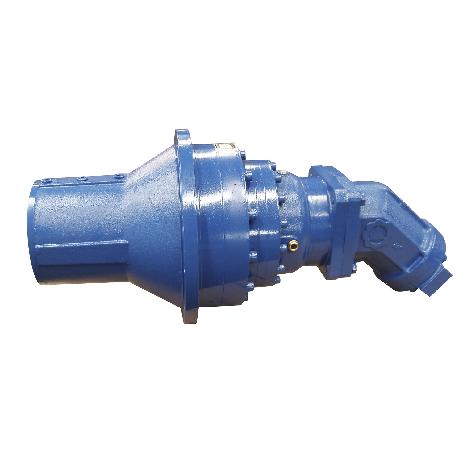
Key feature:Planetary gearbox is produced by modular design, and can be combined according to client...
See Details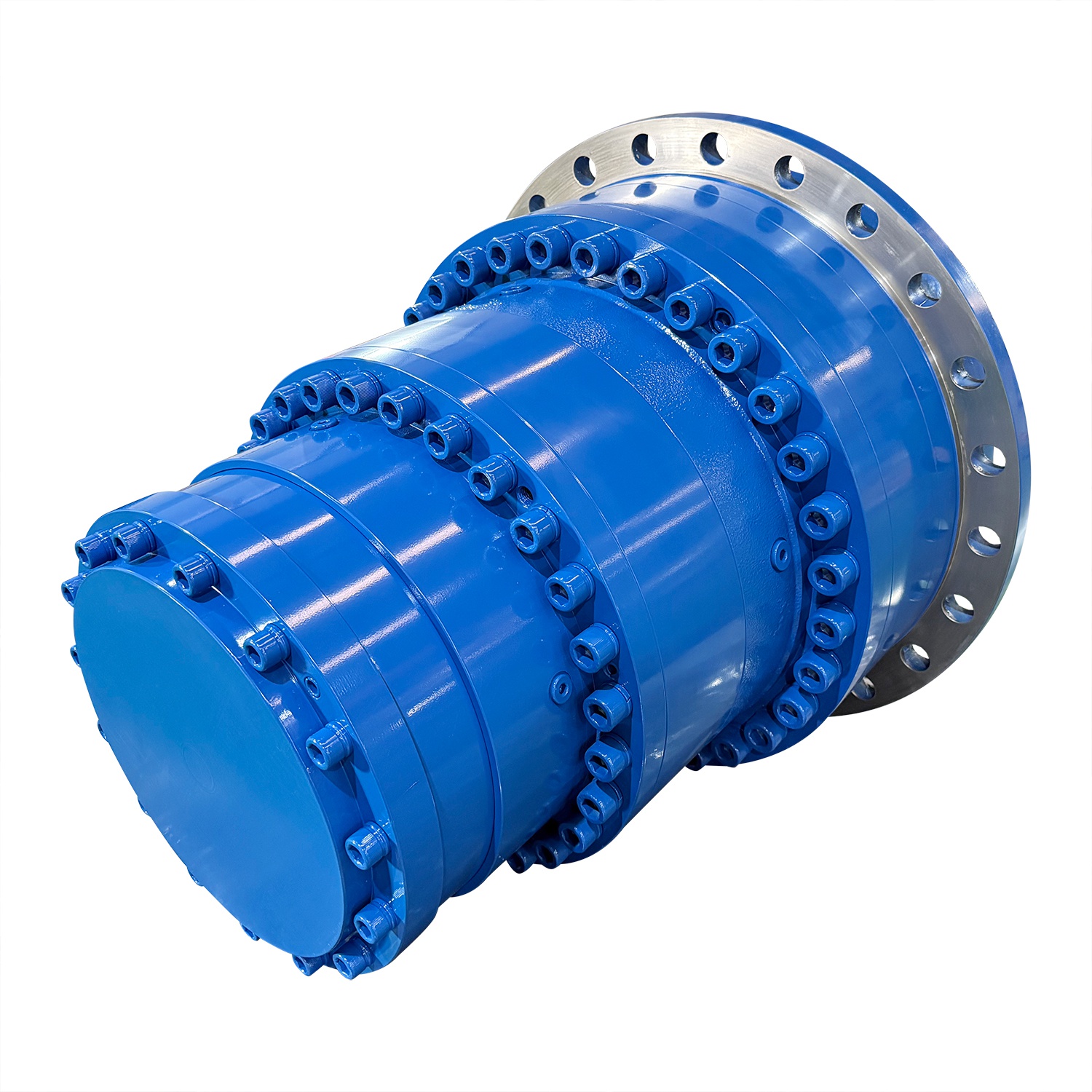
Planetary gear reducers serve as key transmission parts for sightseeing boats sailing along Russia’s...
See Details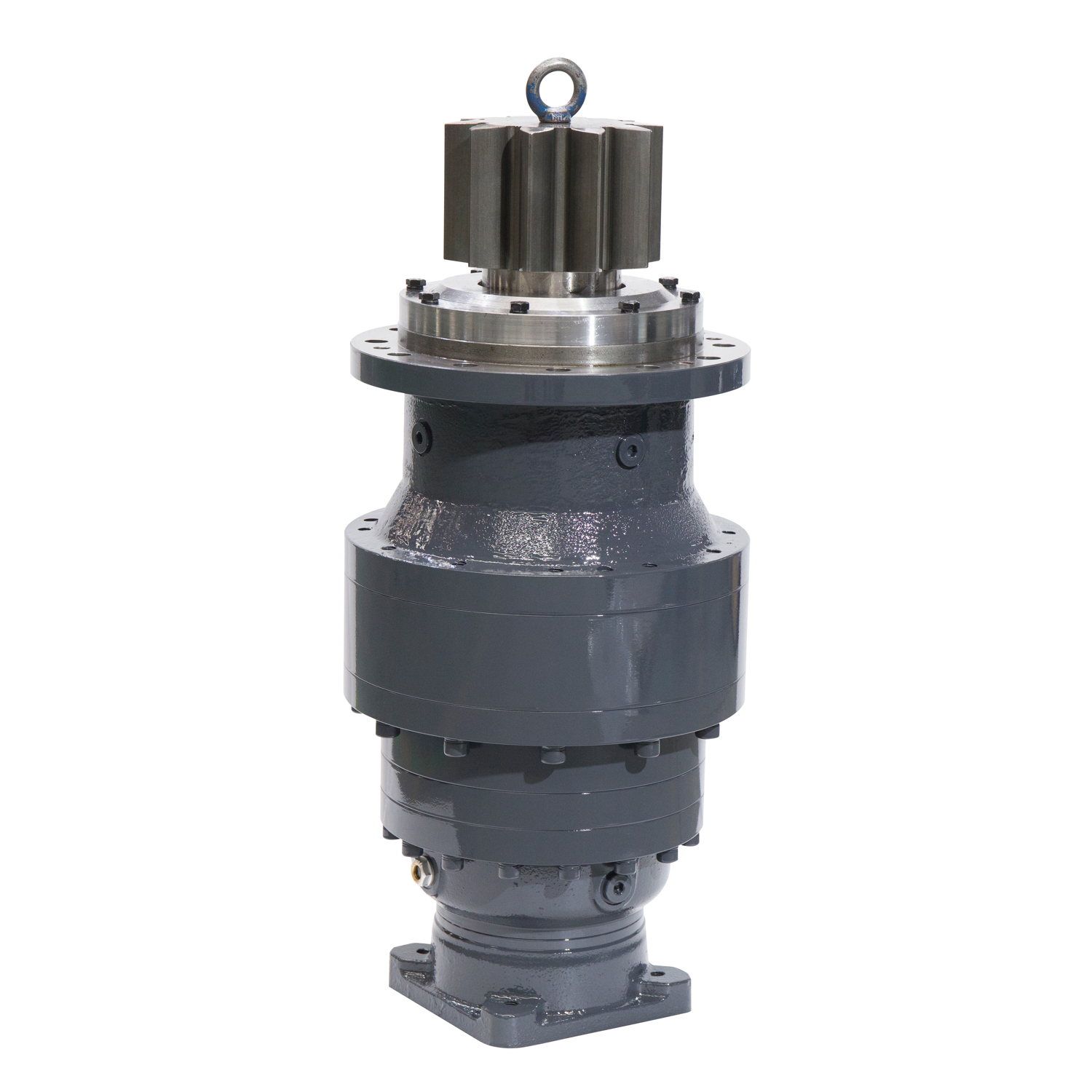
Model: 200-885Ratio: 3.15-7800Output Torque :1500Nm-540000NmRating Power :0.25KW-200kwDescription : ...
See Details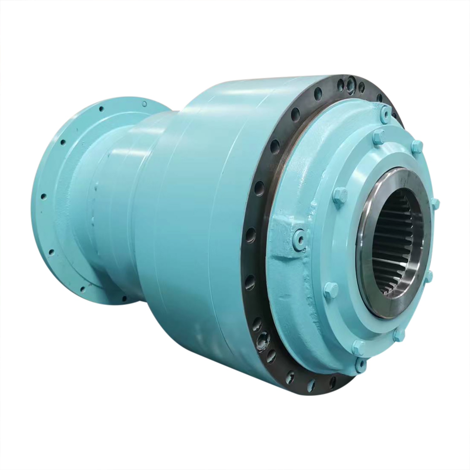
Planetary Gearbox Application For In Electric Drive Model: 200-885Ratio: 3.15-7800Output Torque :15...
See Details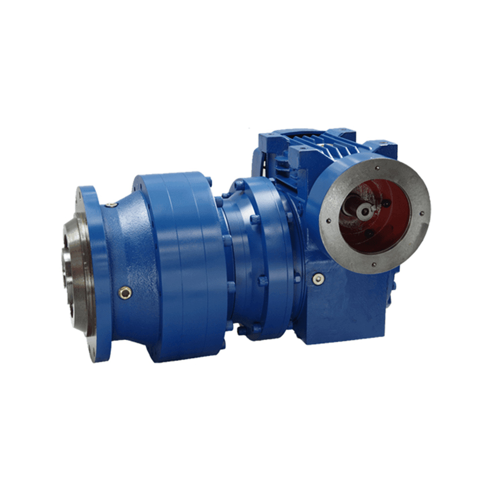
The planetary and toroidal worm combined reducer developed by SGR features a compact structure, with...
See Details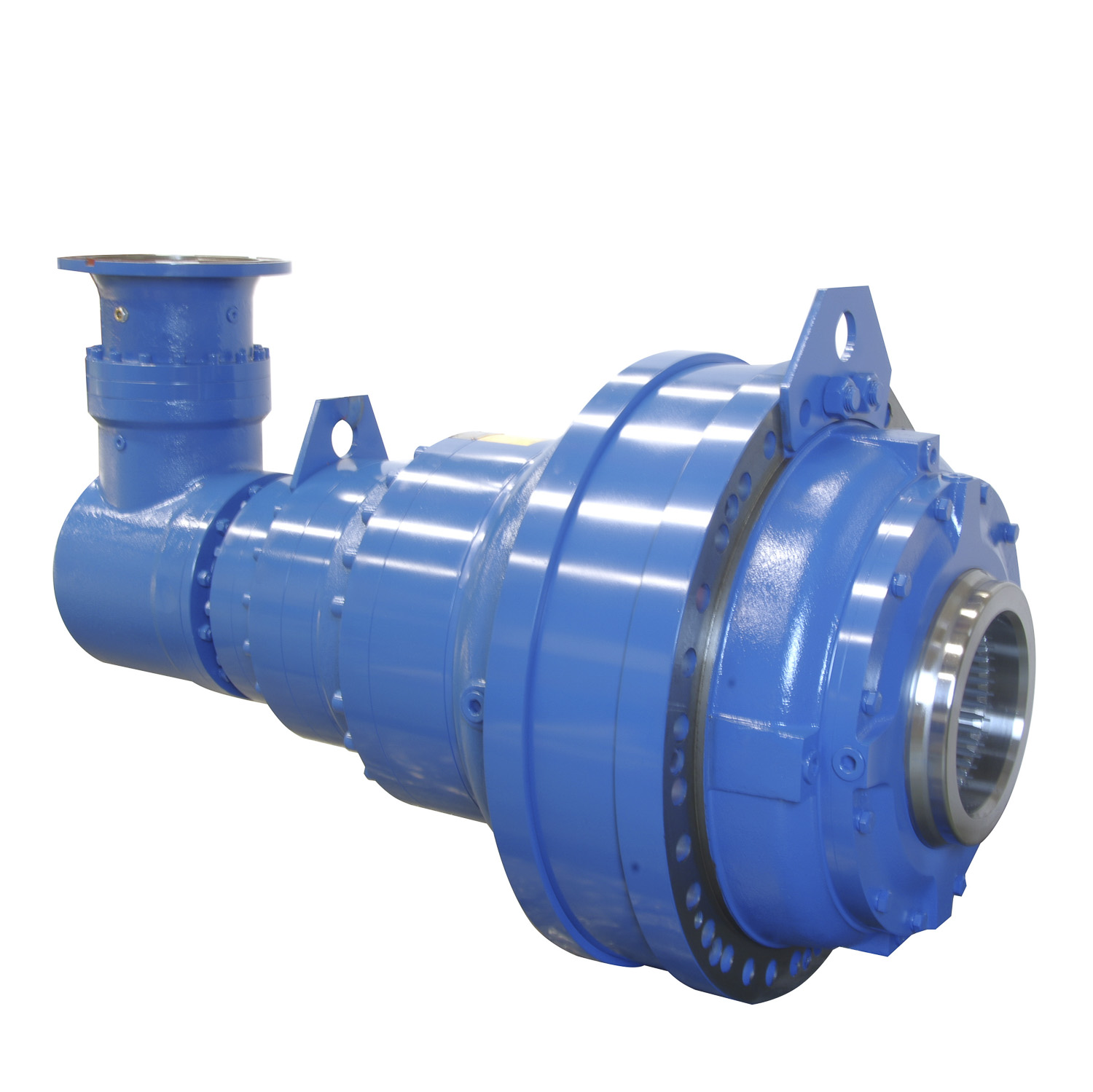
Planetary gearbox is produced by modular design, and can be combined according to client's request H...
See Details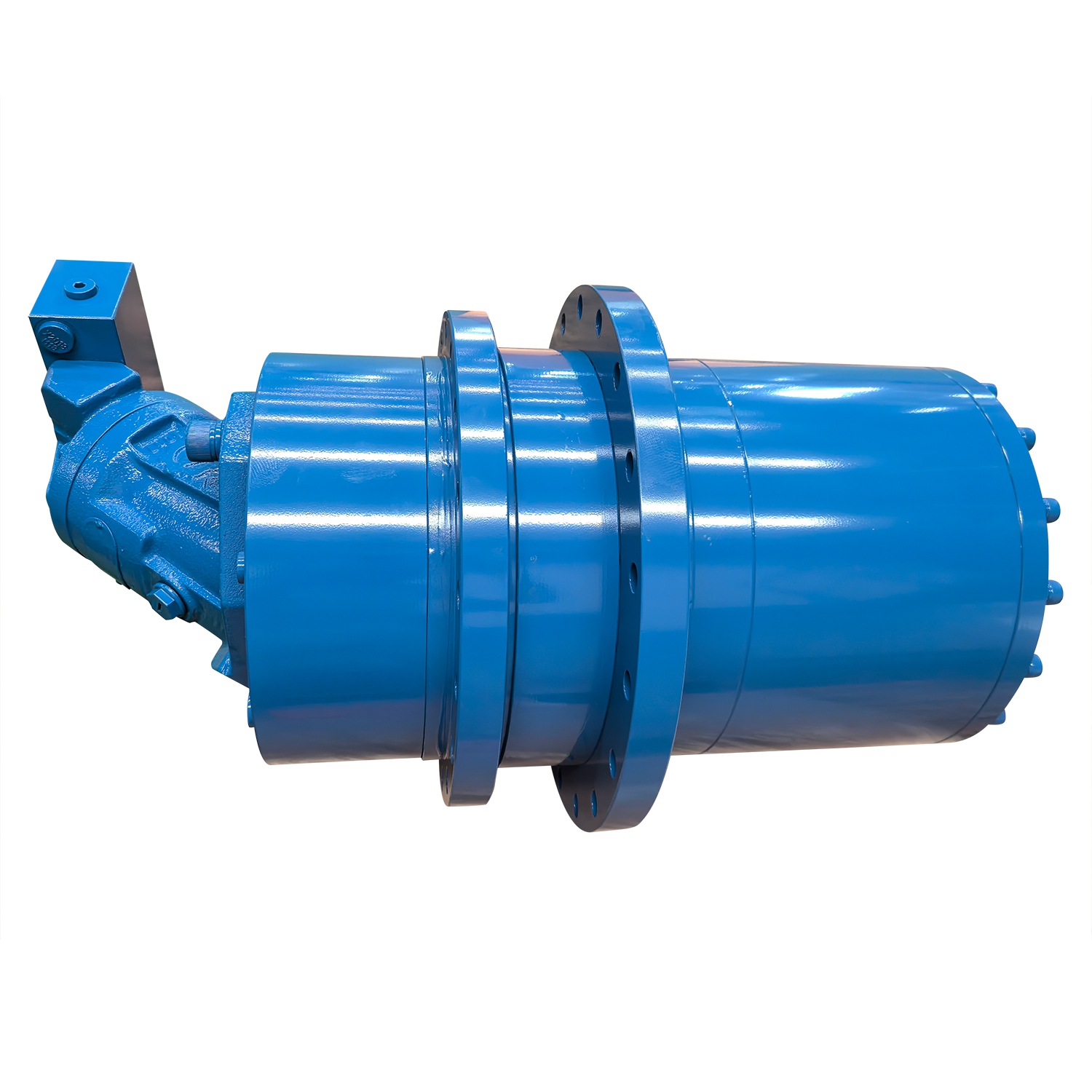
Model: 200-885 Ratio: 3.15-7800 Output Torque :1500Nm-540000Nm Rating Power :0.25KW-200kw Descripti...
See Details
SGR is an ISO 9001 certified, DNV-accredited industry gearbox manufacturer since 1996. We supply different gear reducers to brands worldwide.