 English
 中文简体
中文简体 русский
 Español
SGR's N Series high torque coaxial planetary gearbox Input forms: N standard shaft input, MN flange ...
See DetailsNews Directory
Many people are familiar with the double-enveloping worm gear reducer; it is a "familiar face" in the field of industrial power transmission, widely used across various industrial and mechanical sectors thanks to advantages such as a compact structure, smooth transmission, and the ability to achieve high reduction ratios.
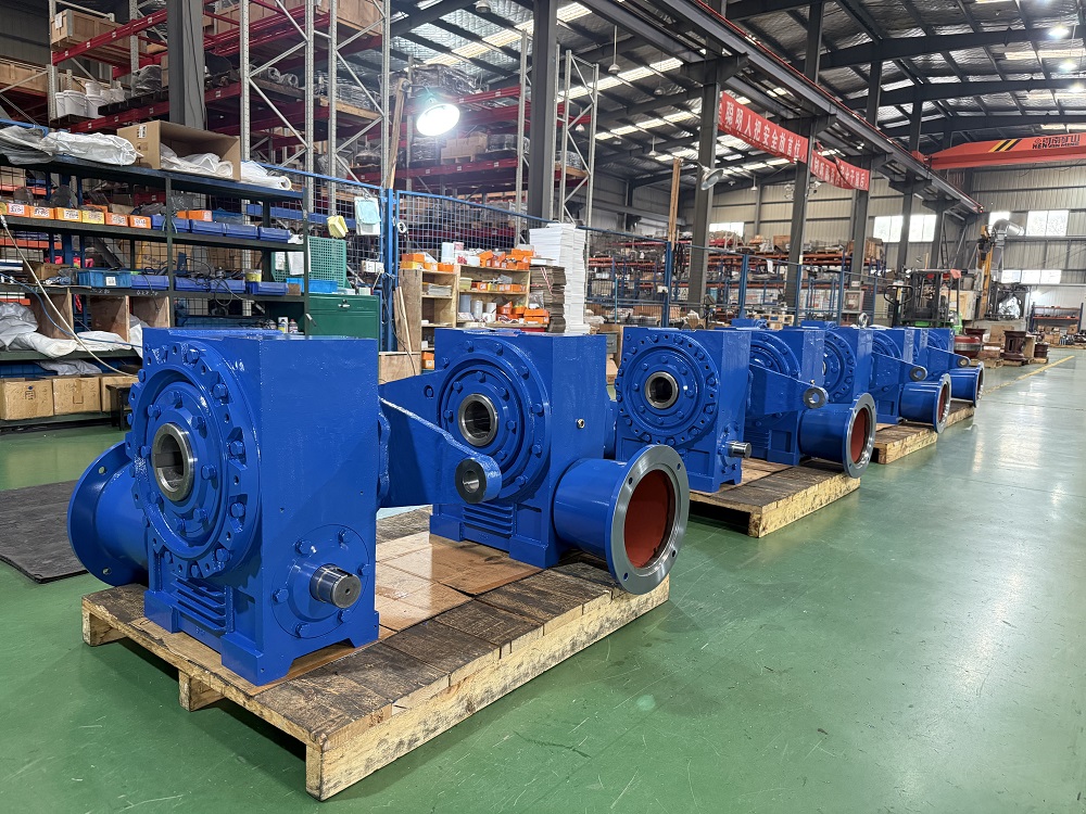
In recent years, an increasing number of people have begun purchasing double-enveloping worm gear reducers. So, what is the difference between a double-enveloping worm gear reducer and a conventional worm gear drive?
Conventional worm gear drives typically employ a cylindrical worm meshing with a helical gear, this arrangement results in point or line contact, a small actual load-bearing area, and susceptibility to stress concentration, leading to rapid wear and low efficiency.
The unique feature of the double-enveloping toroidal worm gear reducer lies in its "double-enveloping" structure. During worm machining, a complex curved surface is generated through two enveloping motions, enabling simultaneous multi-tooth engagement with the worm gear. This creates a high-contact-ratio drive characterized by a combination of surface contact and multi-line conjugation. The advantages of this meshing method are evident: the contact area is significantly increased, thereby substantially enhancing load-bearing capacity.
The perception that worm gear drives suffer from low efficiency is deeply ingrained.Standard worm gear drives typically operate at only 40%–70% efficiency—a figure that drops significantly as the reduction ratio increases—primarily due to intense sliding friction between the worm and the worm gear tooth surfaces. Furthermore, the load-carrying capacity of conventional worm gear drives is modest, making them suitable for light-to-medium load applications.
In contrast, double-enveloping worm gear reducers offer high torque density and load-carrying capacity. They excel in applications requiring high output force and compact installation, while also demonstrating superior resistance to impact loads and wear.
It is precisely the differences in mechanical performance that lead to vastly different application ranges for conventional worm gear drives and double-enveloping worm gear reducers. Double-enveloping worm gear reducers are widely used in applications demanding extremely high reliability—such as metallurgical rolling mills, mine hoists, marine steering gear, and heavy-duty construction machinery—whereas standard worm gear drives are typically employed in settings like conveyor belts and general industrial equipment.
Conventional worm gear drives feature a simple structure, mature manufacturing processes, low costs, and suitability for mass production.
In contrast, double-enveloping worm gear reducers utilize a complex worm surface geometry that requires specialized CNC machine tools and precision gear-grinding processes; consequently, they are difficult and time-consuming to manufacture, entail higher costs, and represent a relatively new type of transmission equipment.
For instance, the double-enveloping worm gear reducers developed and manufactured by SGR are characterized by multi-tooth meshing between the worm and the worm gear. The worm is made of 20CrMnTi steel—subjected to carburizing, quenching, and precision grinding—while the worm gear is made of high-performance alloy bronze, ensuring long-lasting wear resistance, high transmission efficiency, and an extended service life. Compared to cylindrical worm gear sets of the same specifications, these reducers offer significantly higher load-bearing capacity and transmission efficiency; furthermore, they exhibit mechanical self-locking capabilities at high gear ratios, effectively enhancing the safety of hoisting machinery.
Worm gear reducers operate based on the principle of sliding friction. Their reduction ratios typically range from 5:1 to 100:1; generally, the higher the reduction ratio, the smaller the lead angle and the lower the efficiency. When selecting a worm gear reducer, it is necessary to balance the reduction ratio against efficiency and choose a model that meets the requirements for both.
Additionally, for prolonged operation, heat dissipation measures must be considered—such as installing fans or oil cooling systems, or selecting a cast-iron housing equipped with cooling fins.
The materials and manufacturing processes of worm gear reducers are critical determinants of their performance. Leading manufacturers typically use alloy steel (such as 20CrMnTi) for the worm and tin bronze (ZCuSn10P1) or aluminum bronze for the worm gear—materials that offer excellent wear resistance and low friction. Components undergo carburizing, quenching, and grinding to achieve high hardness and enduring wear resistance, resulting in high transmission efficiency and a long service life.
In contrast, if cast iron is substituted for the worm gear material in inferior products, the service life is drastically reduced.
Addressing the issue at the source by selecting a trustworthy and reliable manufacturer of worm gear reducers can save a great deal of trouble. If the reducer is intended for use in specialized equipment—such as marine vessels, elevators, or lifting machinery—it is advisable to verify whether the manufacturer holds the relevant industry certifications; for marine applications, for instance, certification from the Russian Maritime Register of Shipping (RS) is highly desirable.(Author, SGR, Angie Zhang)
WhatsApp: +86 188 1807 0282

SGR's N Series high torque coaxial planetary gearbox Input forms: N standard shaft input, MN flange ...
See Details
Product Info: The MNC3E400 series high speed and high torque industrial planetary gear reducers are ...
See Details
Center distance: 100~710 mm Speed ratio: i ≥ 10. Design modularization, specification serialization,...
See Details
Center distance: 100~710 mm Speed ratio: i ≥ 10. Design modularization, specification serialization,...
See Details
SGR develops and manufactures specialized worm gear reducers for logistics machinery attachments. T...
See Details
SGR develops and manufactures specialized worm gear reducers for logistics machinery attachments. T...
See Details
The planetary and toroidal worm combined reducer developed by SGR features a compact structure, with...
See DetailsSGR is an ISO 9001 certified, DNV-accredited industry gearbox manufacturer since 1996. We supply different gear reducers to brands worldwide.
