 English
 中文简体
中文简体 русский
 Español
SGR's N Series high torque coaxial planetary gearbox Input forms: N standard shaft input, MN flange ...
See DetailsNews Directory
Planetary gear reducers, also known as epicyclic gear systems, consist of three main components: the sun gear, planet gears, and ring gear. The sun gear sits at the center while multiple planet gears rotate around it, all enclosed within the ring gear. This compact arrangement provides several advantages over traditional gear systems.
Compared to parallel shaft gear reducers, planetary gear reducers offer higher torque density, better load distribution, and more compact dimensions. The load gets shared among multiple planet gears, allowing for greater torque capacity in a smaller package.
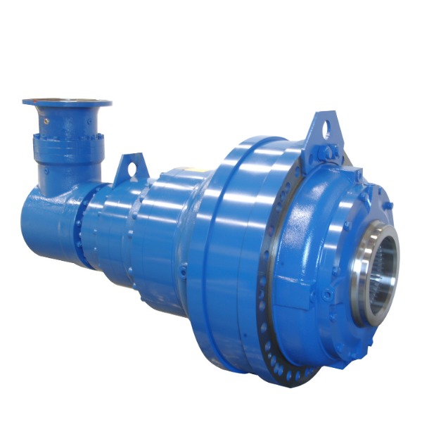
Flange Input Right Angle Big Output Torque Planetary Gearbox with Motor
The unique architecture of planetary gear systems provides several performance benefits:
Selecting the proper gear ratio is crucial for optimal performance. The ratio determines the relationship between input speed and output torque. Common ratios range from 3:1 to 100:1 for single-stage designs, with multi-stage units offering ratios up to 10,000:1.
Several considerations influence the ideal planetary gearbox ratio for an application:
| Application Type | Typical Ratio Range | Considerations |
|---|---|---|
| Robotics | 10:1 to 100:1 | Balance between speed and precision |
| Wind Turbines | 50:1 to 100:1 | High torque requirements |
| Conveyor Systems | 5:1 to 20:1 | Moderate speed reduction needed |
Proper maintenance significantly extends the service life of planetary gear reducers in industrial applications. These systems often operate under demanding conditions, making regular care essential.
A comprehensive maintenance program should include:
Understanding typical failure mechanisms helps prevent downtime:
| Failure Mode | Root Causes | Prevention Methods |
|---|---|---|
| Gear pitting | Fatigue, contamination, improper lubrication | Proper filtration, correct lubricant selection |
| Bearing failure | Misalignment, overloading, contamination | Precise alignment, proper loading |
When selecting precision reduction systems, engineers often compare planetary gear reducer vs harmonic drive solutions. Each technology has distinct characteristics suited to different applications.
Key differences between the two technologies:
| Application Requirement | Preferred Solution | Reason |
|---|---|---|
| High torque density | Planetary gear reducer | Better load distribution |
| Precision positioning | Harmonic drive | Lower backlash |
Backlash in planetary gear systems refers to the slight movement between meshing gear teeth when direction changes. While some backlash is inevitable, excessive amounts can cause positioning errors and vibration.
Several factors contribute to system backlash:
Techniques to reduce backlash include:
| Method | Effectiveness | Drawbacks |
|---|---|---|
| Preloaded bearings | High | Increased friction |
| Split gear design | Medium | Higher cost |
Robotic applications demand high precision planetary gearboxes that combine accuracy, stiffness, and compact dimensions. These systems must often handle dynamic loads while maintaining positioning repeatability.
Important considerations when specifying gearboxes for robotic applications:
| Robot Application | Critical Gearbox Parameter | Typical Requirements |
|---|---|---|
| Articulated arm | Backlash | <3 arc-min |
| SCARA | Stiffness | High torsional rigidity |

SGR's N Series high torque coaxial planetary gearbox Input forms: N standard shaft input, MN flange ...
See Details
Product Info: The MNC3E400 series high speed and high torque industrial planetary gear reducers are ...
See Details
Center distance: 100~710 mm Speed ratio: i ≥ 10. Design modularization, specification serialization,...
See Details
Center distance: 100~710 mm Speed ratio: i ≥ 10. Design modularization, specification serialization,...
See Details
SGR develops and manufactures specialized worm gear reducers for logistics machinery attachments. T...
See Details
SGR develops and manufactures specialized worm gear reducers for logistics machinery attachments. T...
See Details
The planetary and toroidal worm combined reducer developed by SGR features a compact structure, with...
See DetailsSGR is an ISO 9001 certified, DNV-accredited industry gearbox manufacturer since 1996. We supply different gear reducers to brands worldwide.
