Global
  English
 中文简体
中文简体 русский
 Español
News Directory
Industrial machinery demands transmission solutions beyond standard catalog products. Customized gearbox design translates application-specific requirements—high torque in confined spaces, continuous operation under extreme temperatures, precision speed control—into engineered systems. This guide covers the complete development cycle: requirement analysis, precision design, advanced manufacturing, and quality validation that transform industrial performance.
Standard gearbox catalogs contain hundreds of variants. Yet 40% of industrial machinery cannot use off-the-shelf solutions. Space constraints, unusual speed ratios, extreme load profiles, or specialized environments force designers toward custom gearbox manufacturing. Engineering precision directly predicts performance: transmission efficiency, noise signature, vibration, thermal stability, and service life all emerge from the design phase.
Customized gearbox development starts with rigorous application analysis. Engineers evaluate operating conditions, load profiles, space constraints, and environmental factors. This intelligence drives every subsequent decision—gear type selection, material choice, manufacturing tolerance, assembly strategy.
Before manufacturing begins, engineers use finite element analysis (FEA) and computational fluid dynamics (CFD) to predict stress concentration, heat generation, vibration modes, and fatigue life. Simulations identify design weaknesses that prototypes would reveal too late—after costly machining and assembly.
Design precision translates to manufacturing precision. CNC machining holds tolerances (±0.05mm on critical surfaces). Gear hobbing produces teeth within ISO Grade 6. Heat treatment hardens gears to 58–62 HRC. Surface grinding removes distortion. Quality checkpoints—dimensional inspection, gear runout verification, bearing press-fit verification—validate every assembly step.
CMM (coordinate measurement machine) inspects 100% of critical dimensions: gear OD, bore runout, tooth profile, shaft concentricity. Zero tolerance for deviations beyond ±0.02mm on gear mesh.
Finished gears undergo single-flank runout testing to verify tooth geometry. Noise testing confirms quietness below specification (typically below 75 dB @ rated load). Vibration analysis detects resonance conditions.
Gearbox tested under 120% rated torque for 8 hours. Temperature monitoring ensures thermal stability. Oil analysis post-test detects abnormal wear particles indicating incipient failures.
Extended testing protocols validate 20,000+ hour service life under continuous duty. Documentation includes design calculations, material certificates, dimensional records, and test reports for traceability.
Customized gearboxes power automation, manufacturing, heavy industry, and energy systems. Each application demands distinct engineering: robotics requires compact, backlash-free designs; mining equipment needs extreme durability and shock resistance; wind turbines require efficiency optimization and thermal management.
Design and engineering: 2–4 weeks. Manufacturing: 3–6 weeks depending on complexity. Testing and validation: 1–2 weeks. Total: 6–12 weeks for standard configurations. Expedited orders possible with premium pricing, but quality standards remain unchanged.
Alloy steel gears withstand high loads and fatigue cycling. Stainless steel suits corrosive environments but requires adjusted cutting parameters. Cast iron housings dissipate heat well but add weight. Aluminum reduces weight by 40% but sacrifices thermal conductivity. Material selection balances load capacity, environment, and weight constraints.
Helical gears typically achieve 95–98% efficiency. Planetary systems reach 96–98%. Worm gearboxes operate at 60–90% (lower due to sliding friction). These efficiencies assume proper lubrication and alignment. Real-world efficiency may drop 2–3% if installation deviates from design specifications.
Yes, if mounting interfaces and power ratings are compatible. Engineers design around existing motor size, frame dimensions, and input/output shaft locations. Adaptors may be required, adding cost and lead time. Pre-retrofit site surveys prevent installation surprises.
Oil analysis detects incipient gear wear (elevated iron, copper content indicates spalling). Vibration monitoring identifies bearing degradation and misalignment. Temperature trending reveals lubrication breakdown or cooling system failure. Condition-based monitoring extends service intervals and prevents catastrophic failure.
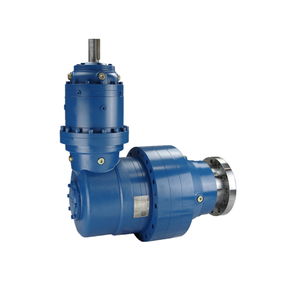
Technical data: 1. Ratio range: 3.15-30002. Input power: 0.25-55KW3. Permit torque rang: ≤ 200000N. ...
See Details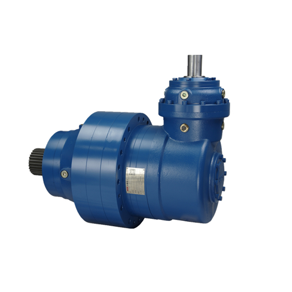
Technical data: 1. Ratio range: 3.15-30002. Input power: 0.25-55KW3. Permit torque rang: ≤ 200000N. ...
See Details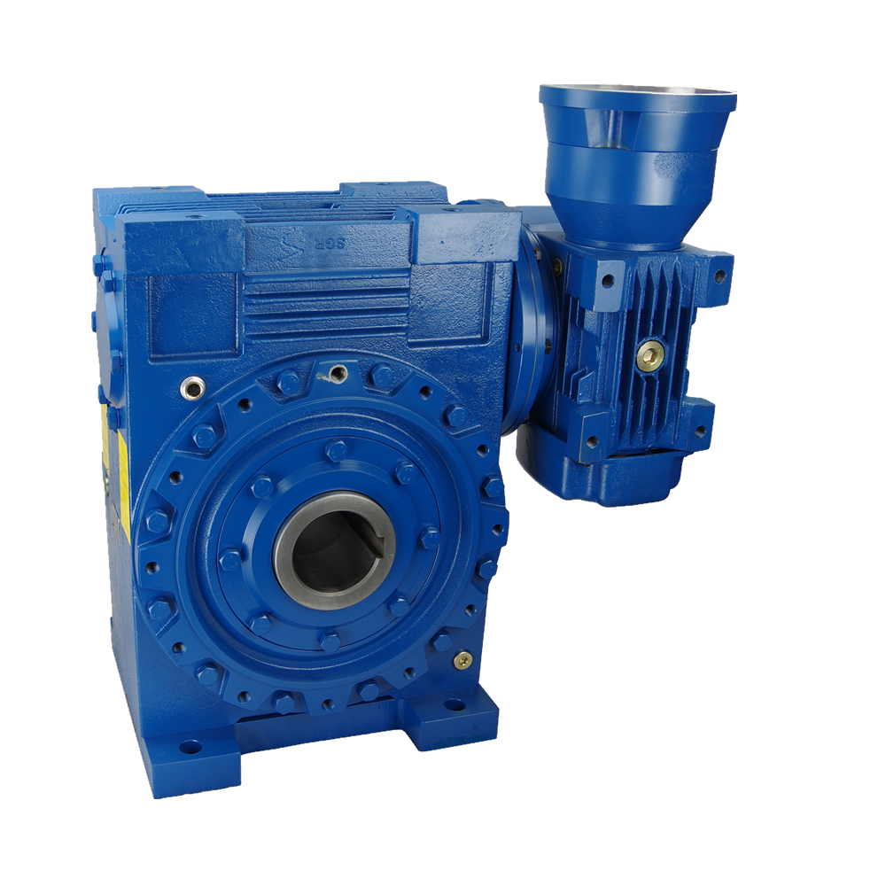
Product Description Series C double enveloping worm gearModel: 100 - 500Ratio: 10 -63Output Torque ...
See Details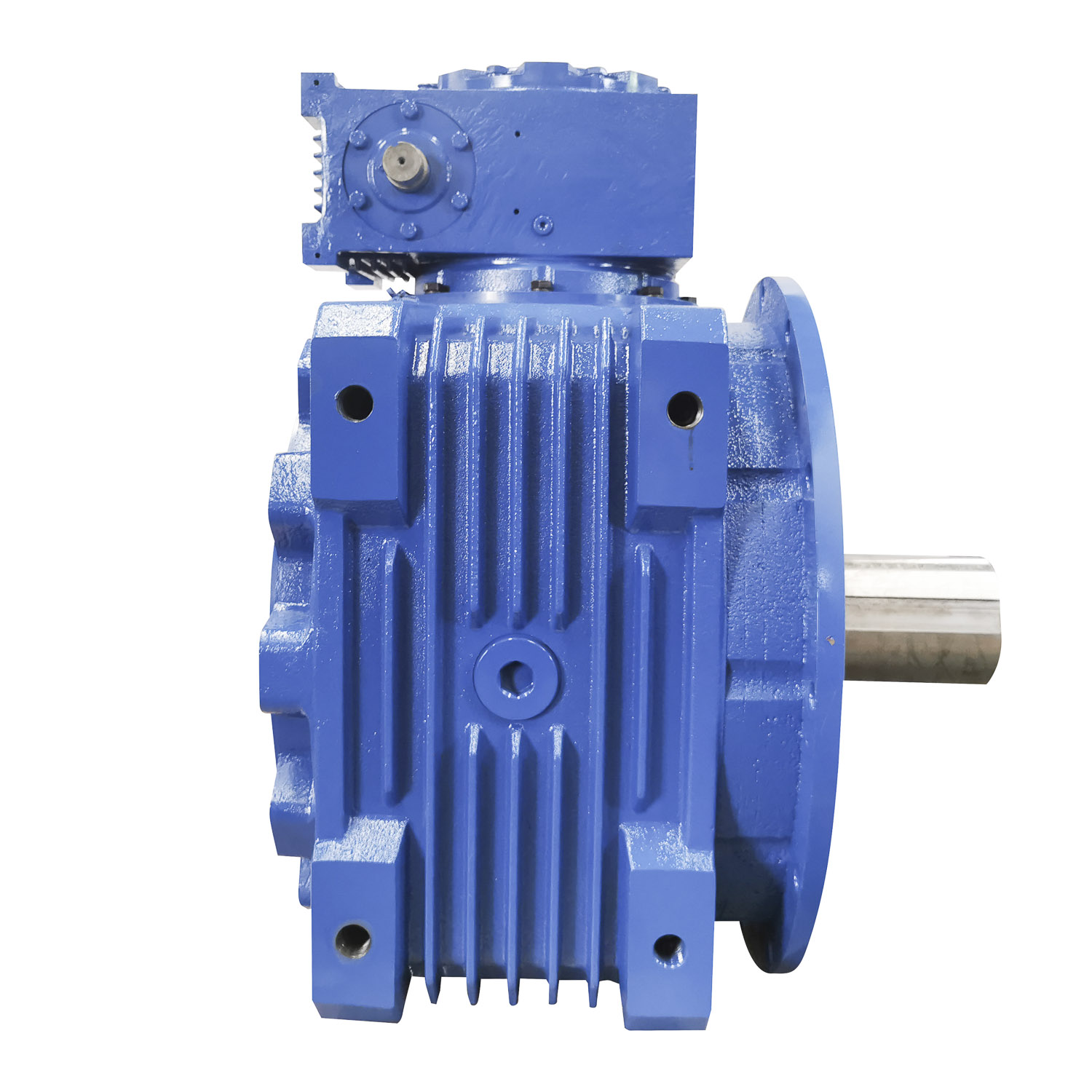
Description :1, High torque double enveloping worm gear adjust toughest working condition .2,Univers...
See Details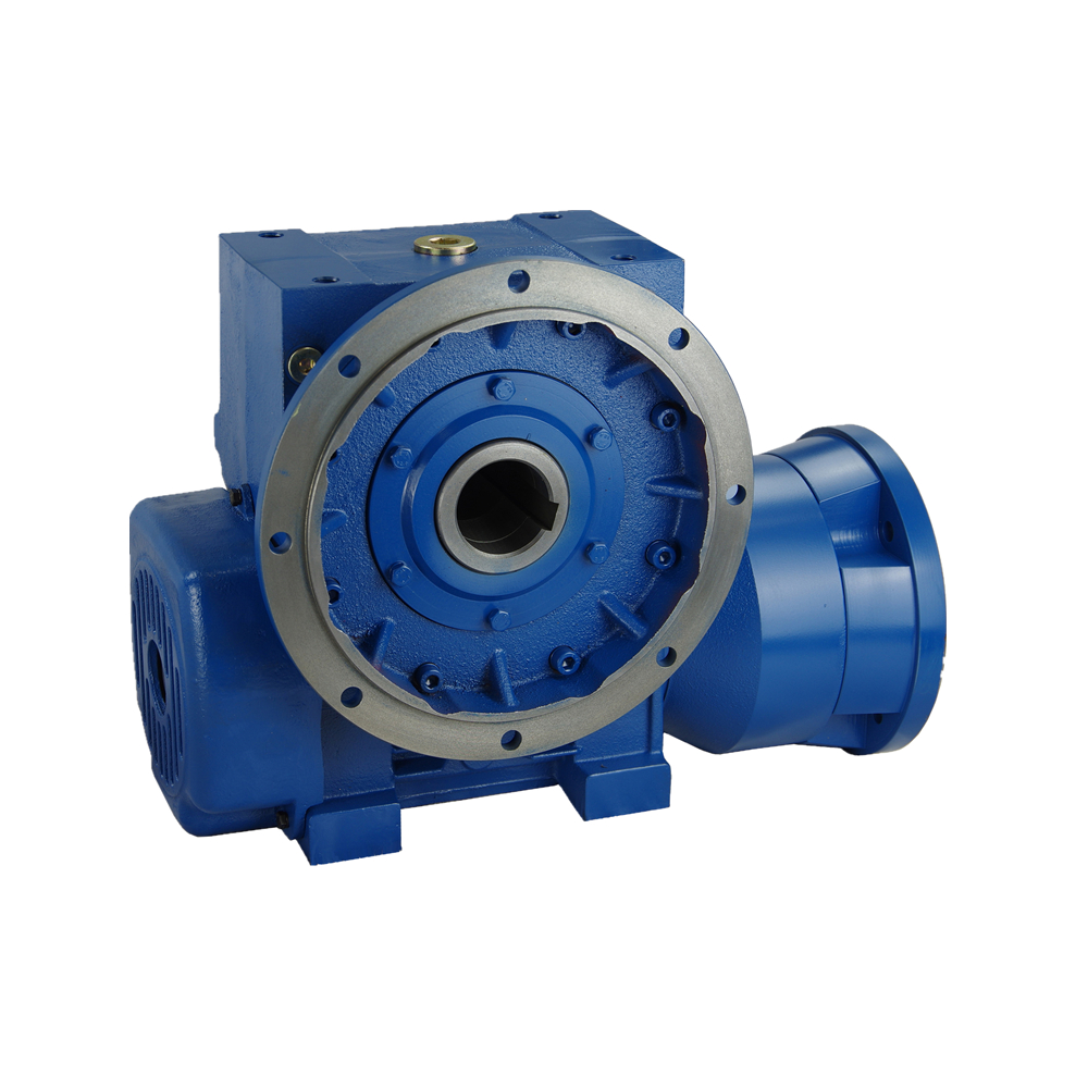
Product Description Series C double enveloping worm gearModel: 100 - 500Ratio: 10 -63Output Torque ...
See Details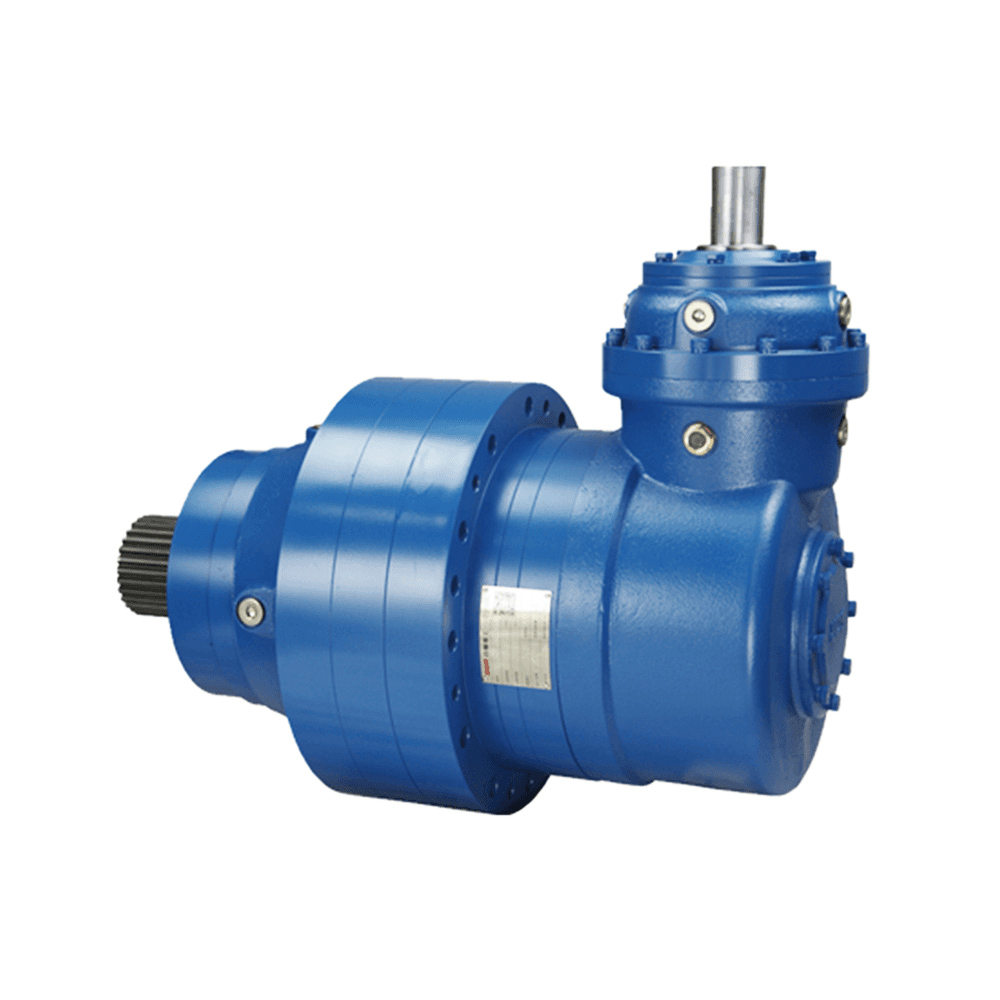
Product Info: The MNC3E400 series high speed and high torque industrial planetary gear reducers are ...
See Details
SGR is an ISO 9001 certified, DNV-accredited industry gearbox manufacturer since 1996. We supply different gear reducers to brands worldwide.